What is Potentiometer Taper?
Potentiometer taper is the relation between the position of the potentiometer and the resistance ratio. In the majority of variable resistors available this is a linear relationship, meaning that the relative position is equal to a percentage of the resistance ratio. For instance, when the pot is at the middle position, the output voltage is half of the full voltage. For some applications and especially audio volume control, non-linear, logarithmic tapers are used.

ISL Products can offer a wide variety tapers, but we specialize in audio tapers. Over the years, we have manufactured potentiometers with over a dozen different types of audio taper. There is no need to settle for an “off the shelf” option when ISL can supply you with exactly what you need. Along with the various tapers we offer, we can also help design pots that are being used in an abnormal or harsh environment.
Types of Taper
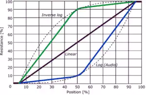
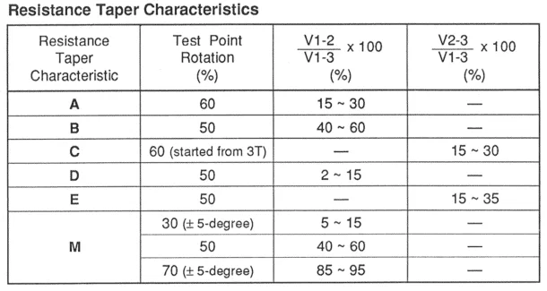
The most common type is the linear taper (Taper B in the graph below). When we plot the position against the resistance ratio we can visualize the different position-resistance relations. The graphs below show the most used tapers. The first and last few percent of travel are often only mechanical with no change in resistance. The region between 5 and 95%, where the electrical resistance changes, is called electrical travel. The available travel for rotary pots is often denoted in degrees, a mechanical travel of 300° combined with an electrical travel of 270° is common. The most used non-linear taper is the logarithmic (log) or audio taper (Taper A in the graph below). This is mainly used for audio volume control, to obtain a more natural ‘linear’ perception in sound intensity change when you adjust the volume. Due to the fact that the human ear is sensitive to sound intensity in a logarithmic fashion, at low sound intensities a small change in intensity is perceived as a big change in loudness. On the other hand, at high intensities, a large change is required for the same change in perceived loudness. To compensate for the ears logarithmic behavior, audio taper pots were developed. While it is called logarithmic, it is actually an exponential curve (the opposite of the logarithmic behavior of the human ear).
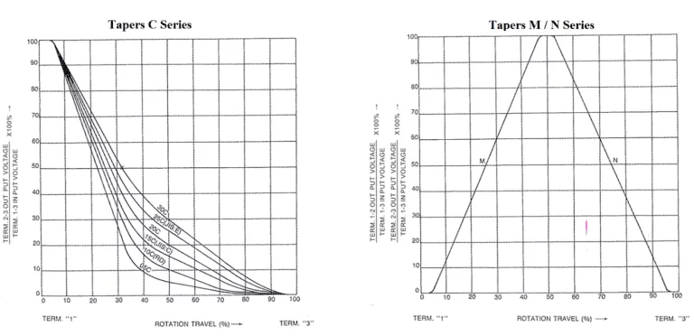
Sometimes reverse logarithmic pots are used (Taper C in the graph below), for example in audio controls that turn counterclockwise, but also in some other specialized applications.
In some applications, a dual taper with a center detent is needed (Taper M/N in the graph below). The M taper has 0% to 100% output voltage from 0% to 50% rotation (linear) & 100% output voltage from 50% to 100% rotation. On the other hand, the N taper is the complete opposite with 100% output voltage from 0% to 50% rotation & 100% to 0% output voltage from 50% to 100% rotation (linear). Full output for both M & N tapers at 50% rotation (center detent).


