
Find ISL Products Online at 


Design Note
DC Motors and Small DC Gear Motors – The Basics
Enhance performance and efficiency in your next design with our high-torque DC motors & small DC gear motors
Introduction to DC Motor Fundamentals
DC motors and small gear motors are pivotal components in modern electromechanical design, responsible for transforming electrical energy into mechanical motion. By precisely tweaking voltage and current, engineers can achieve highly accurate control over speed and torque. When these motors are paired with specialized gearboxes, they become even more effective, delivering massive torque at lower speeds for demanding industrial, medical, and consumer applications.
Understanding DC Motors
At their core, DC motors convert electrical energy into mechanical energy through electromagnetic induction. This conversion occurs via the interaction of magnetic fields induced by direct current flowing through the motor’s internal coils.
In a standard DC motor, the torque production directly correlates to the electrical current drawn by the device. As current increases, the magnetic force strengthens, thereby enhancing the overall torque output. Conversely, the motor’s rotational speed is directly proportional to the voltage supplied. This linear, easily calculable relationship allows for precise operational control, making DC motors the go-to solution for applications demanding rapid responsiveness and variable speed limits.
What is a Gear Motor?
A gear motor is the highly efficient integration of an electric motor and a mechanical gearbox (often called a speed reducer). This combination optimizes performance and drastically increases a motor’s versatility.
- The Motor: Generates the raw, high-speed rotational motion. Most commonly, either a brushed or brushless DC motor is utilized.
- The Gearbox: A complex system of gears engineered to alter the output torque and speed of the motor. Depending on the specific gear ratio (for example, 48:1), the gearbox will significantly multiply the motor’s mechanical torque output while concurrently reducing its rotational speed.
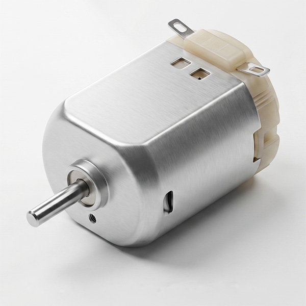
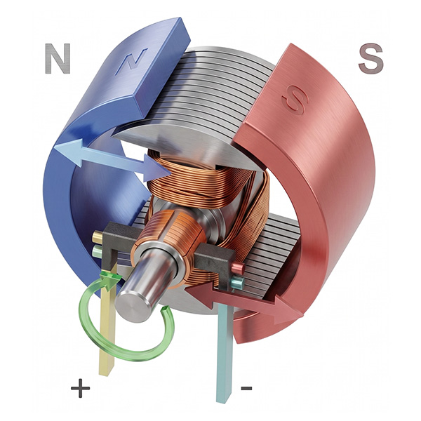
This adaptation makes gear motors strictly indispensable for tasks where high pulling or pushing force and meticulously controlled speeds are required within a compact footprint.
Key Motor Characteristics and Parameters
When selecting a motion control solution, engineers must evaluate several critical parameters to ensure optimal performance and long-term reliability.
- Speed and Torque: Speed is quantified in revolutions per minute (RPM), while torque is typically measured in pound-inches (lb-in), ounce-inches (oz-in), or kilogram-centimeters (kg-cm). There is an inverse relationship between the two when utilizing a gearbox; as torque output increases, speed decreases.
- Voltage and Current: DC motors must operate at their rated voltages to achieve peak efficiency. Operating below this threshold diminishes power, while exceeding it risks catastrophic overheating. Understanding stall current (the maximum electrical power draw when the motor is completely stopped under a heavy load) versus running current is crucial for evaluating battery life and thermal limits.
- Gear Ratio: The mathematical ratio that determines exactly how much the gearbox will reduce the base motor’s speed and amplify its torque at the output shaft.
Primary Types of DC Motors
- Brushed DC Motors: Utilize mechanical carbon brushes and commutators to deliver straightforward, cost-effective power. They are dependable but require eventual maintenance due to physical brush wear and friction over time.
- Brushless DC Motors (BLDC): Eliminate mechanical brushes entirely in favor of electronic commutation via a motor controller. They offer superior electrical efficiency, quieter completely silent operation, and a virtually maintenance-free extended service life.
- Planetary Gear Motors: Combine a standard DC motor with a highly compact planetary gearbox to deliver incredibly high torque output within space-constrained environments.
- Spur Gear Motors: Feature a straightforward parallel-shaft gear arrangement that translates motor rotation into reliable motion for general applications requiring moderate torque and budget-friendly integration.
- Stepper Motors: Move in highly precise, discrete magnetic steps, making them the optimal choice for accurate positioning and repeatable movements (like 3D printing) without the need for complex external feedback systems.
How to Read Motor Performance Curves
A motor’s true capabilities and limitations are mapped out on a performance curve graph, displaying the relationship between key operational metrics:
- Speed (RPM): A straight line showing the inverse relationship with torque.
- Efficiency (%): A parabolic curve calculated by dividing mechanical output by electrical input. Motors should be designed geared to operate as close to their peak efficiency as possible.
- Torque: The physical mechanical load borne by the shaft, typically represented on the X-axis.
- Current (A): Indicates the direct relationship between electrical amperage draw and mechanical torque output.
Common Applications
Because of their massive versatility and scalable sizes, DC gear motors are utilized across countless global industries:
- Robotics and Automation: Driving robotic arms, precision wheels, and automated actuators with absolute speed control.
- Automotive: Powering heavy-duty window lifts, windshield wipers, and motorized seat adjusters.
- Medical Equipment: Delivering quiet, highly reliable operation in delicate surgical tools, medical fluid pumps, and powered patient wheelchairs.
Partnering with an applications engineer early in the conceptual design phase ensures that your chosen motor’s voltage, current, speed, and torque perfectly align with your product’s specific operational demands.
