EMI, or electromagnetic interference, is a disturbance within an electronic device. This disturbance is usually caused by some outside energy source. EMI can be generated from many sources including: radio frequency (RF) transmitters and receivers; power lines; computers; phones; televisions; microwave ovens; electric motors; fluorescent lights; and other electrical devices.
The type of equipment and other electronic components being used within the electrical system or general environment of a given device need to be considered when determining the susceptibility to EMI.
There are two types of interference; radiated and conducted. Radiated interference travels in the form of radio waves, also called radio-frequency interference or abbreviated as RFI. Conducted interference is caused by physical contact or the very close proximity of electrical conductors.
Conducted Interference
An electrical device is susceptible to conducted emissions from its own electrical path, usually from a power source or other devices connected to it. This type of interference originates from lower frequencies generated by other electronics within a system or grid. The noise propagates along various power cables and other wire connections. It can affect other devices in operation connected to the source of the interference.
Conducted susceptibility is the ability of a device to operate effectively despite being impacted by energy and information transmission through power cords or other connections.
Radiated Interference
In similar fashion to conducted emissions, radiated emissions is RF noise being generated by a device without any physical contact. Radiated interference is caused by RF signals generated by high powered devices, external sources, or even components within a system. These higher frequencies interfere with a device’s operation and tracking down the source of the interference can be tricky.
Every electronic device is required to operate within a predetermined spectrum. If a device is generating RF outside of the spectrum, it can interfere with other devices. The Federal Communications Commission (FCC) regulates the use of radio frequency energy in order to protect the public from harmful interference and to promote efficient use of the electromagnetic spectrum.
The FCC has established specific bands for different types of communications services. For example, cellular telephones are allocated certain frequencies on the radio frequency spectrum that they may not be allowed to transmit on unless they have been licensed by the FCC.
DC Motors and EMI
DC motors inherently generate a lot of electrical noise, especially the brushed variety. The constant switching of electromagnetic fields inside a motor creates rapid changes in voltage and current which may affect neighboring conductors. Arching caused by the brushed commutation inside of these motors acts as a large source of radiated emissions. It’s also important to consider that systems built around a DC motor, such as relay arrays or Pulse Width Modulation (PWM) drivers, can also generate emissions and induce frequencies onto other devices. It is important to note that EMC compliance is related to an OEM’s (original equipment manufacturer) finished product and not the responsibility of the individual component manufacturer or supplier.
Interference Testing and Mitigation
Electromagnetic Compatibility (EMC)
During conducted susceptibility testing, an electromagnetic compatibility (EMC) test lab will wire up the device in question to a test rig. During this procedure, they will introduce signals to the cables via various electrical equipment. The device will be subjected to a wide range of frequencies and measurements will be taken to determine how susceptible that device is to EMI. The frequencies transmitted in each test are determined by the certification standard the device needs to achieve.
The industry and country the end device will be used/sold in will dictate the EMC requirements that a product must comply with. For example, medical devices or industrial products follow IEC standards for EMC. Military products are measured for EMC as per MIL standards.
Conducted Emissions
Similar to conducted susceptibility testing, conducted emissions testing is focused on cables and connectors. Instead of looking at what is being transmitted to the device, the lab will look at which frequencies the device is transmitting. This is common for different types of power supplies.
Radiated Susceptibility
Radiated susceptibility testing involves transmitting signals towards a device. The signals to be transmitted are determined by the specific EMC test standard requested. These tests are implemented to determine if a device’s operations will be impacted by the signals. Different types of devices have different definitions of failure, so the level it impacts a device’s operation is determined by the manufacturer and test standard. For instance, a flicker on a television screen might be acceptable, but a flicker on a plane’s navigation system is not.
EMI Mitigation
There are various ways of reducing EMI – electromagnetic interference issues. Grounding or shielding cables can reduce conducted EMI. A common solution for reducing conducted interference on wires and cables is to implement a ferrite bead or choke to help suppress excess noise.
Using a shielded enclosure can help improve immunity while at the same time reduce radiated emissions. Conductive material is the best for shielding, better known as a Faraday cage. Physical shielding provides signal attenuation through reflection and absorption of electromagnetic waves.
For dc motors, one common mitigation method is to attach a decoupling capacitor between the terminals of the motor. This helps reduce EMI by removing high frequency signals. Finding the potential sources of EMI within a device is one of the most challenging aspects of an electrical system.
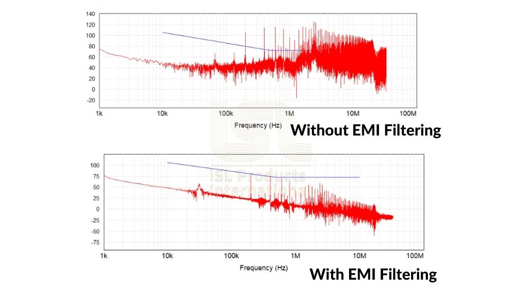
In the example noted below, we illustrate two different examples of EMC test results. The top graph is testing without any EMI filtering. The bottom graph shows the results with EMI filtering implemented.

The blue line on both graphs represents the maximum interference level allowed for this test. You can see from the results that the EMI filtering significantly reduces the emissions well below the allotted levels, especially at the higher frequency levels.
It is important to note that EMC regulations relate only to the operation of completed electronic equipment–an empty enclosure cannot comply. This level of testing and compliance with test standards can be costly, but your due diligence can help ensure the successful design of your application.


