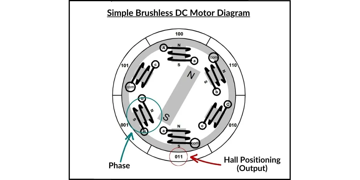
Brushless, and brushed DC motors share the same type of current, but the similarities are few and far between. Unlike a brushed DC motor, brushless DC motors are constructed with field windings in the stator and permanent magnets in the rotor. Since the motor windings are stationary, permanent connections can be established to energize them. Stator slots are wound such that when they are energized it creates its own electromagnetic field that opposes the permanent magnetic field of the rotor. Since the rotating magnetic field generated by the stator causes the rotor to revolve at the same frequency, BLDC motors can be referred to as “synchronous” motors. Brushless motors can come in one, two, or three-phase designs, with three-phase motors being the most common.
Winding commutation relies on sensing the rotor position, then energizing the phases in a sequence that will produce the most amount of torque. In practice, the max torque is produced when the permanent magnet is 90° from alignment with the stator magnetic field. The rotor travels 60° per commutation step, so a stator current path is activated when the rotor is 120° from alignment with the stator, and then deactivated when the rotor is 60° from the corresponding stator field. Then the current path is activated to the next (succeeding) stator field and the process repeats. An accurate and easy way to commutate stator windings is by utilizing a position sensor, such as a hall-effect sensor.
Brushless DC Motor Application Note

Typically, three sensors are offset from each other by 60 degrees, and output a digital “High” signal is generated every 180 degrees of electrical rotation, with a digital “Low” signal for the other 180°. Offsetting the sensors allows the output signal to be in alignment with each one of the phase circuits. The output signal, a unique 3-bit code, corresponds to the rotors N-S pole position relative to the stator.
3 Types of Electronic Commutation Schemes
There are three electronic commutation schemes: Trapezoidal, Sinusoidal and Field-Orientated Control (FOC). We will look at all methods of control in brief detail to outline their differences. All three types will require a bldc motor controller for proper functionality.
BLDC Motor Selection Tips & Advice
Trapezoidal Commutation
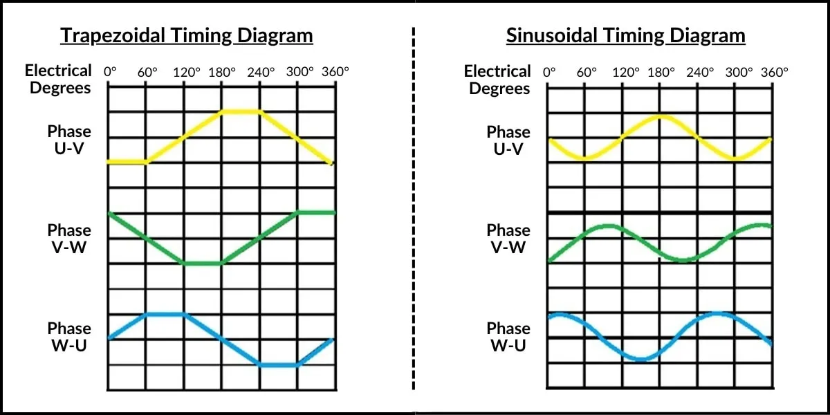
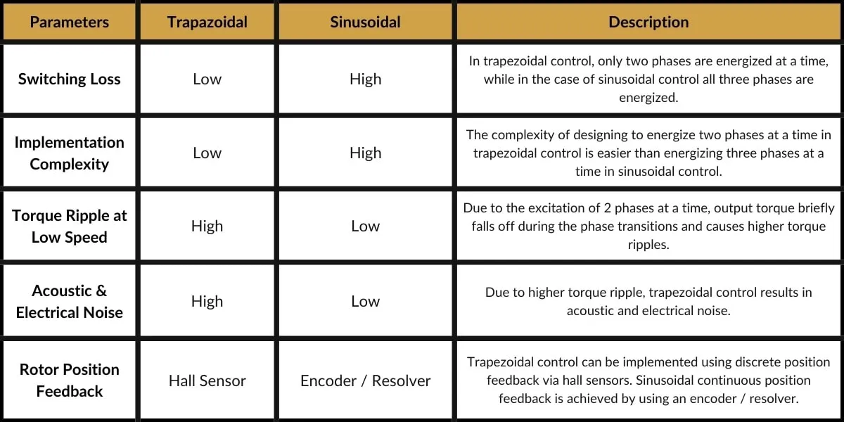
Trapezoidal is the most common type of motor commutation because it is the simplest technique. At each step, 2 windings are energized while the 3rd winding is set to a “float” position. In a motor employing a trapezoidal control, the 3-phase switching must occur in a precisely defined sequence for the BLDC motor to operate efficiently. The switching sequence is determined by the relative positions of the rotor’s magnet pairs and the stator’s windings. 3-phase BLDC motors requires a six-step commutation sequence to complete one electrical cycle. The relationship between the mechanical revolutions and the electrical cycle is dependent of the pairs of magnets attached to the rotor. One downside to this method of commutation is that, between commutation steps, there is a torque “ripple” phenomenon. This ripple causes oscillations in the motor’s torque delivery.

Sinusoidal Commutation
Sinusoidal commutation energizes all three stator coils, with a (sinusoidally) varying drive current that’s 120° separated from phase-to-phase. This results in a much smoother power output delivery. In order to generate smooth sinusoidal modulation of the phase currents as the motor turns, an accurate measurement of rotor position is required. Hall devices provide only a coarse measure of rotor position and are inadequate for this purpose. For this reason, angle feedback from an encoder, or similar device, is required.
Sinusoidal commutation results in a smooth rotation that is generally unachievable with trapezoidal commutation. However, while it is very effective at low motor speeds, it tends to fall apart at high rotational maximum speeds. As speed increases, the current loop controllers must track a sinusoidal signal with increasing frequency. This is computationally intensive, high level processing hardware and software tools are needed to mitigate this problem, but in-turn increasing the cost of a system. At the same time, the drive circuit must overcome the motor back-EMF, as this parameter also increases in amplitude and frequency as speed increases. When this happens, less torque is produced by a given amount of current, and therefore more motor current is required to maintain torque. In short, efficiency begins to deteriorate.

Field Oriented Control (FOC)
Field Oriented Control, or FOC for short, relies on measuring and changing stator currents so that the angle between the rotor and stator magnetic field(flux) is always at 90° – the position of highest leverage and thus, highest torque output. At high speeds FOC is more efficient than sinusoidal commutation, while outperforming all other methods during dynamic load changes. With Field Oriented Control, there is virtually no torque ripple. Smoother, more precise control can be achieved at both low and high speeds. FOC motors, in addition to Sinusoidal controlled motors, can be referred to as Permanent Magnet Synchronous Motors (PMSM).
It is also worth mentioning that, sensor-less commutation is possible by “sensing” the back-EMF voltage on an un-driven phase circuit. A properly programmed micro-controller can monitor the relative position of the rotor to the stator without the need of a Hall sensor. This simple motor construction reduces cost and, in some instances, increases reliability since there is less supporting hardware involved in its construction. However, motor start-up can be tricky since a stationary motor does not generate back-EMF. A clever pathway, using open loop BLDC motor control, must be implemented to start the motor until enough back-emf is generated for micro-controller detection.
Shop Brushless DC Motor Controllers
Conclusion
In conclusion, DC brushless motor designs can vary depending on the application and use-case. Each type has been developed to address a range of constraints and desired performance characteristics. The level of sophistication or simplicity involved make these types of electric motors great options for a wide range of DC based systems.


