

At ISL Products we manufacture a range of electric motors and gear motors for the purpose of meeting the specific needs of our customers. There are many variables that determine what the optimal gear motor solution will be, such as size constraints, voltage, output shaft orientation, rotational speed, and direction of rotation. However, there is one parameter that can be the ultimate deciding factor – output torque requirements.
A motor converts electrical energy into mechanical energy. A gearbox is often coupled to a motor to reduce the output speed and increase torque output. Sometimes, though, the mechanical energy generated by the gearmotor is a bit too much for a gearbox to handle.
To explain the importance in understanding these gearbox torque limits we will first explain what a gear motor performance curve is and their intentions. Then we will help to explain how gearbox torque limitations play a role in determining the optimal motor solution.
Interrupting DC Gear Motor Specifications and Performance Curves
Each of the gear motors that ISL Product produces comes with a detailed specification, better known as a spec sheet or data sheet. Our spec sheets contain gear motor specific information such as physical dimensions and various performance parameters. The performance pentameters are illustrated in a graph format known as a motor performance curve. Each curve shows the relationship between a motor’s speed, current draw, power, efficiency, and most importantly motor torque.
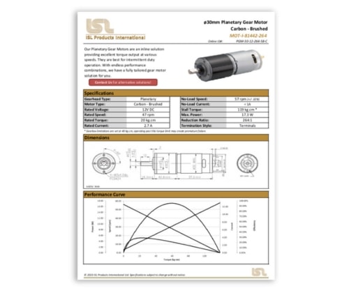
The performance curves illustrate how a gear motor will perform from no load to its stall torque. This helps engineers understand the gear motors tendencies both mechanically and electrically, allowing them to utilize it under the proper duty cycle.
It is important to understand that performance curves are simply projections based on a series of calculations. They’re designed to be a tool that illustrates gear motor performance estimations. In certain instances, mechanical torque limitations may prevent a gear motor from reaching certain load conditions prior to gearbox failure.
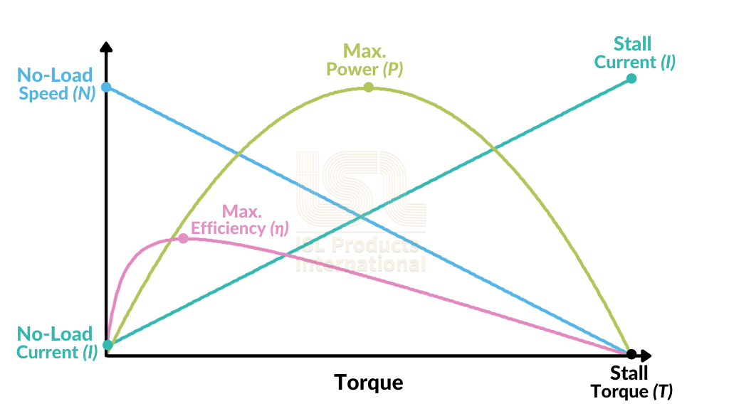
How to Read a Gear Motor Performance Curve
Gearbox Mechanical Torque Limitations
Often misunderstood or overlooked are the gearbox mechanical torque limitations. These limitations are set by the manufacturer and dictate that maximum load or rotational force that a gearbox can safely handle. These mechanical limitations are derived from a variety of factors such as internal gearing and gearbox design.
These limitations are not fully realized in motor performance curves because the primary function of the curve is to illustrate performance projections. Allowing engineers to visualize speed, power, current draw, and efficiency across a wide range of torque measurements.
The mechanical torque output limitations typically come into effect with higher gear reductions as the higher the reduction, the more torque generated. Lower reduction ratios will not have this issue because the materials being used along with the gearbox design can safely withstand the output torques. In some cases, gearbox materials and design may alter expectations.
Internal Gearing Material
Gearboxes are typically made from either plastic or metal. In most cases, your application requirements will dictate which material to use.
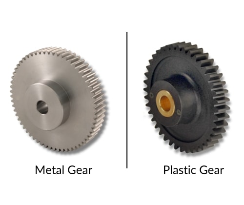
Plastic gears have a lower force threshold than their metal counterparts. Depending on the application though, plastic gearing may be preferred. They are easier and cheaper to manufacture, are self-lubricating, and offer quiet operation. The downside to plastic gears is that they wear quicker and can’t handle high loads.Metal gears, on the other hand, offer a much higher force threshold. In most mass-produced gearboxes, metal gears are made by a process called powder metallurgy. This process takes a mixture of powdered metals and compacts them into the desired gear form, these are then heated while compressed under controlled conditions. A metal gearbox can allow smaller motors to handle larger torque loads.
There are also machined gears, which are made from steel, brass, or mixture of other alloys. These gears are very precise but come with a high price tag.
Gearbox Design
There are three major DC motor gearbox designs: planetary, spur, and worm. Each of these has their own set of advantages and disadvantages. In terms of torque limitations relative to size, worm gear motors can handle the most and spur gear motors the least.
In a spur gearbox, each individual gear is subject to the total load of the gear motor. Therefore, the max torque the entire gearbox can support comes down to the weakest gear.
Planetary gearboxes, by design, distribute the torque load over multiple planetary gears. This in turn reduces the load stress on each individual gear, allowing for a higher max torque output.
Worm gearboxes can produce a much higher gear reduction and offer a load holding ability. These gearbox designs are much larger though in comparison to planetary and spur.
Operating Conditions and How to Increase Gearbox Longevity
Taking it a step further, the physical limitation of a gearbox is just one trait to be aware of. We advise our customers based on their operating conditions as well. Even if a gearbox can tolerate a certain load from a mechanical standpoint, there is also an overall life expectancy to take into consideration.
A gear motor’s optimal performance is typically outlined by its max efficiency (rated) condition. Stall torque estimates are given so that product designers and engineers have a sense of a maximum torque capability, but this can be a bit misleading.
Avoid Sudden Changes in Direction
When a gear motor suddenly changes direction, the momentum of going forwards acts against the new reverse force, temporarily increasing the load on the meshing gear teeth. Sudden changes in direction cause excessive strain and can wear down internal gearing. If the load is high enough, it can even sheer teeth off completely, resulting in a gearbox failure.
The best solution for this would be to reduce the motor speed to 0 rpm, wait one or more seconds, then change direction. This can be accomplished in a few different ways; using PWM (Pulse width modulation), controlled stops, and sudden voltage cuts amongst others. Some gearboxes are designed to only operate in one direction, so be aware of that before implementing any direction changes.
Overloading Will Cause Premature Failure
Applying a load to a gearbox for an extended period, when the gearmotor is at or near its maximum torque limits, will cause significant strain on the entire gear train. This can cause the gearbox to fail much sooner than expected. On all our datasheets, we will note a maximum torque limit, or max momentary torque, if the limit is less than the stall torque and stall current of the gear motor.
To combat this, pay close attention to the datasheet information. If you plan to operate at, or close to, the limits for prolonged periods of time, it’s best to go for a larger motor or gearbox. This will provide you with additional torque headroom and reduce the potential for failure.
Never Hit Physical Stall
Running a DC electric motor or gear motor to its absolute physical stall conditions is considered bad practice. Physically stalling an electrical motor will cause degradation significantly faster than operating at or near max efficiency. In certain circumstances, a motor can fail instantly if it were to hit absolute stall conditions, rendering it useless.
To avoid hitting the physical stall point, the best thing to do is integrate a current limiter into your electronics. This will allow your electronics to cut power to the gearmotor once it reaches a certain amperage, preventing the gearmotor from reaching a physical stall and avoiding catastrophic failure. The best way to calculate the motor current limit is to find the on-load current noted at the max torque limit point on the performance curve, and set the limit lower than the value. This is a great fail-safe to add into any design to help prolong gearmotor life.
Additional Engineering Resources
All the variables mentioned so far can be an overwhelming task to consider. At ISL Products, our engineers take the time to consult and advise prospective customers to fully understand the scope of their project. It’s important that we review all aspects of an application such as current draw, speed, and loads so we may make a better determination of your needs. The information gained from these discussions ultimately aids in the success of your end-product. Our goal is to provide a tailored solution which takes into consideration all the variables your new project presents.
Different motor design or type of motors also play a factor in a gear motor’s performance. ISL Products offers a wide variety of brush DC motors and brushless DC motors that can be coupled with our selection of gear reducers.
* All micro motors and micro DC gear motors manufactured by ISL Products are vigorously tested on unique equipment like a dynomometer, to validate performance.
