

What is a brushed DC motor?
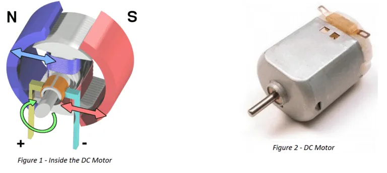
A dc motor or direct current electrical motor is a rotating electro-mechanical device that turns electrical energy into mechanical energy. When dc voltage is applied to the motor terminals, an Inductor (coil) generates a magnetic field that creates rotary motion, as indicated in figure 1 below.
Inside the electric motor is an iron shaft wrapped in a coil of wire. This shaft contains two fixed, North and South, magnets on either side. These magnets causes both a repulsive and attractive force, in turn producing torque. ISL Products designs and manufactures both brushed DC motors and brushless dc motors. In addition, we tailor our DC motor’s size and performance to meet your desired specs.
Shop DC Motors & Gear Motors at our Online Shop
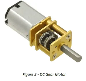
What is a DC Gear Motor?
A gear motor is an all-in-one combination of a motor and gearbox. The addition of a gearbox to a motor reduces the speed while increasing the torque output. The most important parameters in regard to gear motors are speed (rpm), torque (lb-in) and efficiency (%). In order to select the most suitable assembly for your application, you must first compute the load, speed and torque requirements for your application.
ISL Products offers a variety of small or miniature gear motors including Spur Gear Motors, Planetary Gear Motors and Worm Gear Motors to meet all application requirements. Most of our DC motors can be complemented with one of our unique gearboxes, providing you with a highly efficient inline solution. Pairing the proper motor and gearbox reduction ratio is critical when designing in a gear motor.
Search our Motor Solution Database
The Motor Selection Process
Need help determining the right electric motor design for your application? Check out our Motor Selection Guide or Visit the ISL Motor Database.
During the conceptual design phase, the motor selection process can be challenging.
Fortunately, our engineers are here to help. We provide a concierge approach to all of our DC motor and gear motor projects. Our team of engineers work with you to provide the optimal component solution.
The following key points can help you determine and select the most appropriate motion control solution for your application.
- Design Requirements – A design assessment phase where the product development requirements, design parameters, device functionality, and product optimization are studied.
- Design Calculations – Calculations used to determine which motor would be the best solution for your application. Design calculations determine gear ratio, torque, rotating mass, service factor, overhung load, and testing analysis.
- Types of DC Motors – The most common electrical motors convert electrical energy to mechanical energy. These types of motors are powered by direct current (DC).
- Brushed Motor
- Brushless Motor (BLDC)
- Planetary Gear Motor
- Spur Gear Motor
- Stepper Motor
- Coreless & Coreless Brushless
- Servo
- Gear box type
- Motor Specifications – Once the design calculations are performed and the application parameters are defined, you can use this data to determine which motor and gearbox will best fit your application. Some of the most common specs to consider when selecting a solution will be:
- Voltage
- Current
- Power
- Torque
- RPM
- Life Expectancy / Duty Cycle
- Rotation (CW or CCW)
- Shaft Diameter and Length
- Enclosure Restrictions
Motor Performance Curves
A motor’s performance and gearbox performance are combined into one graph by displaying three specific parameters. These three parameters are speed, torque and efficiency. These performance curves are essential when selecting a motor for your application.

- Speed/Revolutions (N) – (unit: rpm) indicated as a straight line that shows the relationship between the motor’s torque and speed. It should be used near its peak efficiency to maximize the motor’s potential.
- Efficiency (η) – (unit: %) is calculated by the input and output values, represented by the dashed line. To maximize the motor’s potential it should be used near its peak efficiency.
- Torque (T) – (unit: gf-cm) this is the load borne by the motor shaft, represented on the X-axis.
- Current (I) – (unit: A) indicated by a straight line, from no load to full motor lock. This shows the relationship between amperage and torque.
- Output (P) – (unit: W) is the amount of mechanical energy the motor puts out.
How To Read Performance Curves
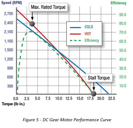
For example, let’s consider the performance curve below (figure 5) for a DC motor.
- Maximum operating efficiency (70%) for this motor would occur at 3.75 lb-in / 2,100 rpm. As noted by the “Max. Rated Torque” plot.
- As torque increases the speed and efficiency decrease. The result of increased torque is poor output performance and the device will eventually fail to function once the motor reaches its stall torque (18 lb-in).
DC motor performance curves are a helpful tool that can be used for a variety of applications. To get the most out of the performance curves it’s important to thoroughly understand your applications’ requirements. It’s important to understand the required load and speed to determine the amount of torque a motor will need to put out. Most DC motor and gear motor manufacturers provide performance curves upon request.
Benefits of using a dc gear motor
DC gear motors can provide several unique benefits, making this type of motor better suited to many applications.
Some benefits of a gear motor include:
- Increased torque: The reduction mechanism increases the torque output, allowing the combined unit to power loads that require more torque than the motor alone can produce. For higher torque applications, you want to use metal gears, as opposed to plastic.
- Reduced speed: The gear reduction mechanism also reduces the rotational speed of the motor’s output shaft. This can be beneficial in applications where high speeds are not required or desirable.
- More efficient power transfer: The gears in a gear motor can transfer power more efficiently than a direct drive motor.
- Compact size and design: Combined power solutions are designed to be space-saving, both inline and right angle options are available. You can get a small DC gear motor, which is beneficial if space is limited.
- Greater flexibility: The ability to adjust the gear ratio to provide the desired operating conditions allows for more control over the torque and speed output, which is helpful in various types of applications.
ISL Products gear motors are widely available, with an excellent range of power and speed. They are also cost-effective and easy to integrate. Their are many types of dc motors to choose from, its best to consult with experts to identify the optimal solution for your next design. Contact an ISL Engineer when you’re ready to get started!
