BLDC Motor Selection Guide
Brushless DC motors can be found in the majority of the electronic devices that we use everyday from computers to cars to power tools. Since their introduction in the 1960s these motors have become the go-to solution for high-power, high-performance products.
There are a lot of aspects in a BLDC motor design that distinguish them from other motor types. This can make selecting the right one for your application incredibly difficult. The team at ISL Products is here to assist! In this BLOG we simplify all things pertaining to brushless motors to get your next project into motion!
How To Select the Right Brushless DC Motor for your Application
Brushless Motor Construction
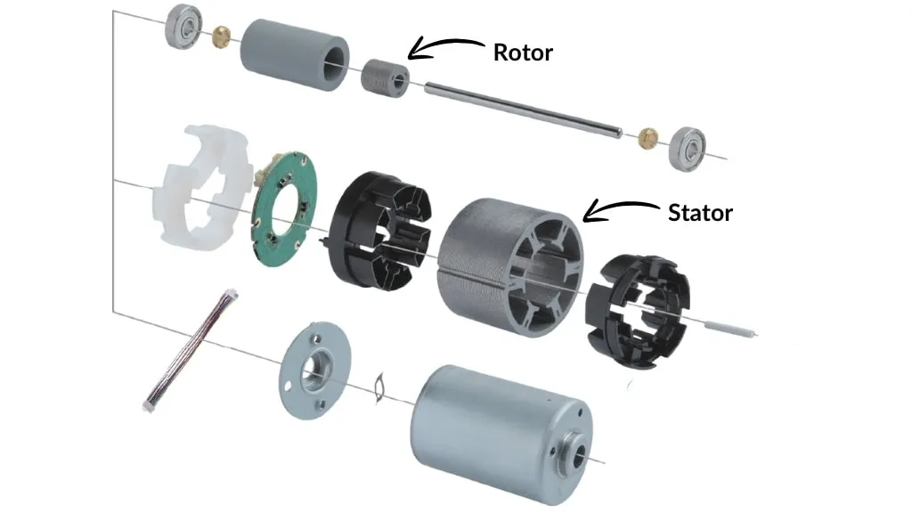
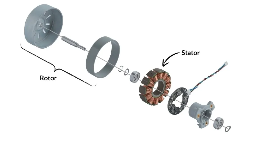
Brushless motors come in two primary constructions, inrunner and outrunner. Their names derive from their rotor locations. An inrunner type of motor has a rotor in the center of the design. On an outrunner, the rotor is in the outer housing, rotating around the center of the motor.
Inrunner Type
An inrunner motor has a simple structure and looks like your typical dc brushed motor from the outside, but that’s where the similarities end. In this construction the coil wound stator surrounds the rotor. The rotor has magnets mounted on its surface. This is considered the standard bldc motor construction.
These motors mount seamlessly into any application previously designed for brushed dc motors and have a wide range of mounting options.
Outrunner Type
Outrunner motors are the reverse construction of an inrunner. An outrunner dc motor consists of a stationary, wire-wound stator and a spinning outer-rotor containing permanent magnets.
This type of motor design allows for additional surface area for magnet placement as well as a larger rotation radius. Since the rotor is larger in diameter, these motors are able to generate more torque. However, since the outside of the motor is spinning there must be additional considerations taken when designing enclosures.
Sensored vs. Sensorless BLDC Motors
In addition to the two different rotor constructions, there are also two different sensor types: Sensored and Sensorless.
Sensored
Sensored motors have 3 hall effect sensors that measure the position of the motor to optimally deliver power to the correct coils at the correct time.
These position sensors allow for a much smoother start up and allow the motor to begin rotating with an initial heavy load on the shaft. This also means that they perform well at low speeds and can be throttled up and down with ease.
Sensorless
Sensorless motors do without the hall effect sensors. Instead, the electronics for sensorless BLDC motors rely on the counter-electromotive force, or “Back EMF” to correctly rotate. As the rotor spins it generates a current on the two sets of coils not currently energized. By monitoring the change in voltage across these coils the controller can figure out where the motor is in its cycle and provide current to the coils at the right speed and in the right order.
Sensorless motors behave better at high speeds and can operate at higher speeds than their sensored counterparts. They are also better suited to harsh environments where dirt, dust, mud, and water may be present.
Their shortcomings are noticed at lower speeds. Back EMF gets stronger the faster the motor is spinning, which makes proper positioning and timing hard at low speeds. This also makes starting a sensorless bldc motor challenging.
Search ISL Motor Component Database
Commutation Options
Brushless motors require a motor controller, this is the tradeoff for not having brushes. Electronic commutation is more efficient and allows brushless motors to be much more powerful than their brushed counterparts. How do you electrically commutate a bldc motor? There are two main options, Internal Drivers and External Drivers.
Internal Drivers
Internal drivers or integrated drivers are small drivers, physically attached inside of a brushless motor. They are specifically designed for each motor’s construction. Typically a PCB slightly smaller in diameter than the motor body, their small form factor and easy integration make them a logical choice for a range of applications where more basic motor function is needed. These drivers tend to be found in simpler designs.
External Drivers
External drivers are a much more common driving method. Often, there is a dedicated drive circuit built into the end-product’s main control board. These drive circuits are typically designed by electrical engineers and offer precise control.
Additionally, there are stand-alone motor drivers, also known as bldc motor controllers, that are designed to be more plug-and-play without additional circuit design. These drivers tend to be larger in size with features like active cooling, terminal blocks, and ports for remote control.
All drivers are designed to operate over a range of input voltages, output voltages, and input currents. As long as a motor has a compatible power rating and phase sequence, the overall physical size and shape of the motor is irrelevant.
Determine Power Requirements
Defining the motor power requirements is key and it will simplify the motor selection process.
Voltage
What input voltage will you need? This is usually determined by the overall system the motor will be a part of. 12V direct current (DC) and 24VDC are our most common offerings. As newer electrical systems are being designed, we are seeing an increased interest in motors that are rated for 36VDC or 48VDC. Many brushless motor drivers are designed to operate over a wide voltage range, making motor and electronic integration a bit simpler.
Current
Brushless motors have higher current ratings. In certain applications, especially battery powered devices, current can be a performance limiting factor. Consider using a smaller, less powerful, motor to better suit application requirements if high current draw is not an option with the motors’ power source. Knowing your maximum current draw limits is a critical part in determining viable motor options.
Power
BLDC motors have a high power density. There are two major aspects to consider though; input power and output power. Input power is calculated using the formula:
Input Power = Current (Amps) * Voltage (Volts)
Tip: Most brushless motor datasheets show output power. Output power is calculated using the formula:
Output Power = Speed (radians/sec) * Torque (Nm)
Output power is illustrated on a performance curve as a parabola, with the maximum output power at the peak. Once you define your power requirements you can then work backwards to select the optimal motor.
BLDC Gear Motors: Speed vs. Torque
Coupling a brushless motor with a gearbox will result in much higher torque outputs. A gearbox reduces the motor’s output speed and converts it into torque. Gearboxes have additional efficiency ratings that need to be used in calculating final output performance like power.
Gearboxes are measured in reduction gear ratios. This is a ratio between the rotations of the output shaft of the motor and the output shaft of the gearbox. For example, a 5:1 reduction gearbox will turn once for every five turns of the motor. This roughly translates to five times as much torque, and one fifth the speed. Our gearboxes come in a variety of reduction ratios, ranging from 4:1 all the way up to 3,600:1 for certain gearbox designs. These combinations result in high performance bldc planetary gear motor solutions.
It’s important to understand that a bldc motor’s maximum speed will range from 5,000 rpm to above 15,000 rpm, which also influences appropriate gearbox pairings. Gearboxes can only handle so much input speed, making proper pairing of the gearbox and brushless motor imperative for reliability and performance.
Duty Cycle
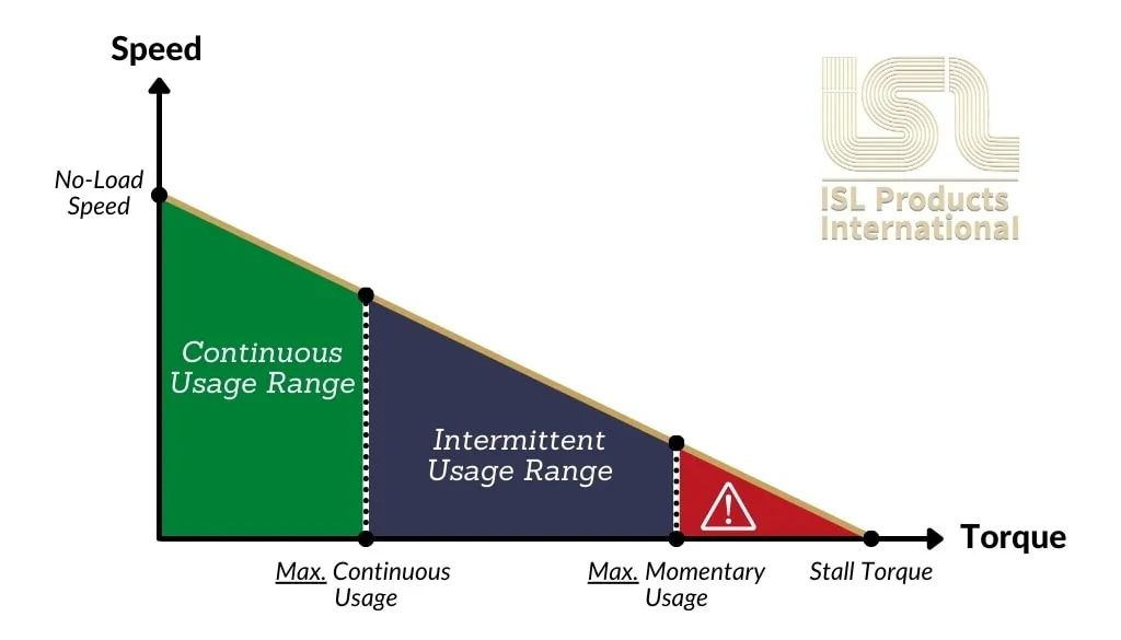
The duty cycle of an electric motor is the relationship between the time doing work and the time spent resting. Examining this ratio will determine the required motor specifications you will need for your application.
Continuous Operation
For continuous use of a motor it is best to utilize less than 30% of the stall torque. This range is where the max efficiency of the motor usually is, allowing for continuous torque output without strain or excess heat building up inside of the motor.
Intermittent Operation
Intermittent use should be considered for torque requirements that are 30-60% of the max torque rating. This allows for slightly undersized motors to perform tasks outside of their ideal range, while still having enough dwell time to cool down. In addition, it will take much longer for the excess wear on the motor to catch up with the application.
Near Stall Conditions / Danger Zone
Once a motor reaches roughly 60% of peak torque capacity it is considered to be in the “Danger Zone”, or maximum momentary torque limit. At this point the motor will begin to overheat, the windings can burn out, and overall use life will decline if the motor continues to operate. Active operation at these levels is only recommended for devices that are single use or spend that vast majority of their life off.
Interpreting BLDC Motor Performance Curves
Most motor curves for BLDC motors can be misleading. The curve does not degrade as linearly as that of a brushed motor. Typically after max power a brushless motor’s performance could fall off significantly, instead of following the same linear pattern to stall conditions. This is even more of a reason to keep the motor operating near its max efficiency point.
Learn more about performance figures and limitations here:
How To Read DC Motor & Gear Motor Performance Curves
All motors have “rated values”. These are the performance figures of the motor while they are operating and max efficiency. In an ideal situation, this is the point at which a motor should be operating to reach its absolute maximum life expectancy.
It can be a challenge to get a motor to align with all these parameters. For any motor selection assistance, you can always contact us. Our engineers are here to help at any stage of a project.
Here are some additional questions you should be prepared to answer:
How Many times will your device be cycled ON and OFF?
As mentioned earlier, operating at max efficiency is important for motors that will be operating consistently.
For most practical applications, the motor does a task, takes a short break, and does the task again. This is considered “intermittent operation”. In situations like this you can use a motor that might be just outside of its recommended range effectively.
Will your device change direction?
This is directed at bldc gear motors. Operating in both clockwise and counterclockwise directions is a common use of dc gear motors and one of the major benefits of utilizing an electric motor. If not done properly though, a gear motor can be damaged beyond repair.
For any gear motor, it’s important to put a dwell in between a change in direction. When a gear motor changes direction suddenly, the high inertia causes mechanical stress resulting in broken gears. Letting the motor slow down to a complete stop and then accelerate again in the opposite direction aids in avoiding these issues, and the life of the gear motor can be dramatically extended.
Since bldc motors alone don’t have many mechanical construction limitations, a sudden change in direction has a minimal effect on the motor itself.
As leading manufacturers and bldc motor suppliers for over 40 years, ISL has an exorbitant amount of experience. We are here to assist our customers however we can. Contact us and discuss your next project with a member of our team today!


